STM32 LibOpenCM3:GPIO 輸出
前言
終於要開始實際寫程式了,接續上一篇的內容,這次要教最基本的 LibOpenCM3 的 GPIO 輸出用法,會控制一個 LED 燈使其閃爍。
正文
先以 Nucleo-F446RE 做示範。
首先建立一個 PIO 的專案,選擇 Framework 為「libopencm3」,並在 src/ 資料夾中新增並開啓 main.c 檔案。
完整程式
先把完整的程式打出來:
/** * @file   main.c * @brief  Blinking LED example for STM32 Nucleo-F446RE. */
#include <libopencm3/stm32/rcc.h>#include <libopencm3/stm32/gpio.h>
/* User LED (LD2) connected to Arduino-D13 pin. */#define RCC_LED_GPIO (RCC_GPIOA)#define GPIO_LED_PORT (GPIOA)#define GPIO_LED_PIN (GPIO5)
static void delay(uint32_t value){  for (uint32_t i = 0; i < value; i++)  {    __asm__("nop"); /* Do nothing. */  }}
int main(void){  /* Enable clock. */  rcc_periph_clock_enable(RCC_LED_GPIO);
  /* Set LED pin to output push-pull. */  gpio_mode_setup(GPIO_LED_PORT,                  GPIO_MODE_OUTPUT,                  GPIO_PUPD_NONE,                  GPIO_LED_PIN);
  gpio_set_output_options(GPIO_LED_PORT,                          GPIO_OTYPE_PP,                          GPIO_OSPEED_2MHZ,                          GPIO_LED_PIN);
  /* Start blinking. */  while (1)  {    gpio_toggle(GPIO_LED_PORT, GPIO_LED_PIN); /* LED on/off. */    delay(500000);  }
  return 0;}
分段說明
Include
#include <libopencm3/stm32/rcc.h>#include <libopencm3/stm32/gpio.h>如同其它的程式,首先要將需要用到的功能 Include 進來。本例中有兩個檔案要引入:
rcc.h:RCC 是 Reset and Clock Controller 的意思,由於基本上所有的 STM32 功能都需要 Clock,因此 RCC 通常是一定會用到的。gpio.h:如如同它的名字,這就是包含了 GPIO 的各種功能。
LibOpenCM3 的這些檔案 PIO 都會幫我們處理好,所以不用另外下載或設定路徑,直接
#include就可以了。
定義腳位
/* User LED (LD2) connected to Arduino-D13 pin. */#define RCC_LED_GPIO (RCC_GPIOA)#define GPIO_LED_PORT (GPIOA)#define GPIO_LED_PIN (GPIO5)因為每個 STM32 Nucleo 開發板的 LED 腳位可能不同,因此使用 #define 來定義腳位比較方便程式的撰寫與修改。
根據資料手冊 UM1724,Nucleo-F446RE 的板載 LED(LD2)所在的腳位是 PA5(對應 Arduino 的 D13 腳位),也就是 GPIO Port-A 的 5 號腳,因此我們定義 GPIO_LED_PORT 為 GPIOA,GPIO_LED_PIN 為 GPIO5。
此外 RCC 也會需要依照 GPIO Port 進行設定,所以也定義一個 RCC_LED_GPIO 為 RCC_GPIOA。
Delay 函式
static void delay(uint32_t value){ for (uint32_t i = 0; i < value; i++) { __asm__("nop"); /* Do nothing. */ }}這是一個最簡單暴力的 Delay 寫法,幾乎無精度可言,但目前我們只要這樣就夠了。
其中的 __asm__("nop") 代表嵌入組合語言的「nop」指令,也就是無操作(No operation)。
主程式
int main(void){  /* Enable clock. */  rcc_periph_clock_enable(RCC_LED_GPIO);
  /* Set LED pin to output push-pull. */  gpio_mode_setup(GPIO_LED_PORT,                  GPIO_MODE_OUTPUT,                  GPIO_PUPD_NONE,                  GPIO_LED_PIN);
  gpio_set_output_options(GPIO_LED_PORT,                          GPIO_OTYPE_PP,                          GPIO_OSPEED_2MHZ,                          GPIO_LED_PIN);
  /* Start blinking. */  while (1)  {    gpio_toggle(GPIO_LED_PORT, GPIO_LED_PIN); /* LED on/off. */    delay(500000);  }
return 0;}-
rcc_periph_clock_enable():這個函式會致能指定功能的 Clock。在這裡我們要啓用 LED 所在的 GPIO Port 的 Clock。 -
gpio_mode_setup():為指定的 GPIO 設定模式。GPIO_LED_PORT:要設定的 GPIO Port。GPIO_MODE_OUTPUT:設定為「General Purpose Output」 模式。GPIO_PUPD_NONE:設定為不使用上下拉電阻。GPIO_LED_PIN:要設定的 GPIO Pin,若要在同一個 Port 中設定多個 Pin,各個 Pin 可以用|來複選。
-
gpio_set_output_options():為指定的 GPIO 設定輸出選項。GPIO_LED_PORT:要設定的 GPIO Port。GPIO_OTYPE_PP:設定輸出電路組態為「Push-Pull(推挽)」 。GPIO_OSPEED_2MHZ:設定速度。GPIO_LED_PIN:要設定的 GPIO Pin,若要在同一個 Port 中設定多個 Pin,各個 Pin 可以用|來複選。
-
gpio_toggle():反轉該 GPIO 的輸出值。如果目前是輸出High,那就變成輸出Low,反之亦然。
編譯與燒錄/上傳
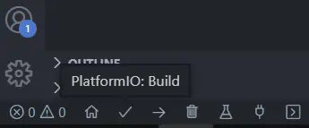
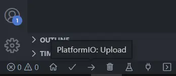
打完程式後,可以在 VS Code 左下方找到編譯(Build)和燒錄(Upload)的按鈕。也可以用快捷鍵「Ctrl+Alt+B」、「Ctrl+Alt+U」。
編譯完成後 PIO 會顯示佔用的資源:
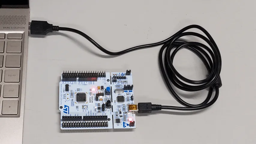
RAM: 0.0% (used 0 bytes from 131072 bytes)Flash: 0.1% (used 764 bytes from 524288 bytes)記得燒錄前要用 USB 線接上 Nucleo,並安裝 ST-Link 的驅動程式,否則會報錯。
F103RB
STM32F1 系列的部分程式寫法不一樣,所以在此也提供 Nucleo-F103RB 的程式範例。主要差異只有 GPIO 的設定函式不同,STM32F1 用的是 gpio_set_mode(),而非 gpio_mode_setup() 與 gpio_set_output_options()。
/** * @file   main.c * @brief  Blinking LED example for STM32 Nucleo-F103RB. */
#include <libopencm3/stm32/rcc.h>#include <libopencm3/stm32/gpio.h>
/* User LED (LD2) connected to Arduino-D13 pin. */#define RCC_LED_GPIO (RCC_GPIOA)#define GPIO_LED_PORT (GPIOA)#define GPIO_LED_PIN (GPIO5)
static void delay(uint32_t value){  for (uint32_t i = 0; i < value; i++)  {    __asm__("nop"); /* Do nothing. */  }}
int main(void){  /* Enable clock. */  rcc_periph_clock_enable(RCC_LED_GPIO);
  /* Set LED pin to output push-pull. */  gpio_set_mode(GPIO_LED_PORT,                GPIO_MODE_OUTPUT_2_MHZ,                GPIO_CNF_OUTPUT_PUSHPULL,                GPIO_LED_PIN);
  /* Start blinking. */  while (1)  {    gpio_toggle(GPIO_LED_PORT, GPIO_LED_PIN); /* LED on/off. */    delay(500000);  }
  return 0;}
PIO 環境
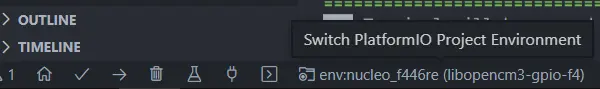
如果你的程式會需要在 F1 或 F4 等其它 STM32 系列上運作,那每次用 F1 時 GPIO 的寫法不同,或是有 Pin 腳不同的情況會很麻煩,所以這裡簡單介紹如何用 PIO 設定多個專案環境,方便切換。
主程式
/** * @file   main.c * @brief  Blinking LED example for STM32 based on LibOpenCM3. */
#include <libopencm3/stm32/rcc.h>#include <libopencm3/stm32/gpio.h>
/* User LED (LD2) connected to Arduino-D13 pin. */#if defined(NUCLEO_F103RB) || defined(NUCLEO_F446RE)  #define RCC_LED_GPIO (RCC_GPIOA)  #define GPIO_LED_PORT (GPIOA)  #define GPIO_LED_PIN (GPIO5)#else  #error "STM32 board not defined."#endif
static void delay(uint32_t value){  for (uint32_t i = 0; i < value; i++)  {    __asm__("nop"); /* Do nothing. */  }}
int main(void){  /* Enable clock. */  rcc_periph_clock_enable(RCC_LED_GPIO);
  /* Set LED pin to output push-pull. */#if defined(STM32F1)  gpio_set_mode(GPIO_LED_PORT,                GPIO_MODE_OUTPUT_2_MHZ,                GPIO_CNF_OUTPUT_PUSHPULL,                GPIO_LED_PIN);#else  gpio_mode_setup(GPIO_LED_PORT,                  GPIO_MODE_OUTPUT,                  GPIO_PUPD_NONE,                  GPIO_LED_PIN);
  gpio_set_output_options(GPIO_LED_PORT,                          GPIO_OTYPE_PP,                          GPIO_OSPEED_2MHZ,                          GPIO_LED_PIN);#endif
  /* Start blinking. */  while (1)  {    gpio_toggle(GPIO_LED_PORT, GPIO_LED_PIN); /* LED on/off. */    delay(500000);  }
  return 0;}
PIO 專案設定檔 platformio.ini
[platformio]default_envs = nucleo_f103rb
; Set/Override default options for each [env:XXX][env]platform = ststm32framework = libopencm3
[env:nucleo_f103rb]board = nucleo_f103rbbuild_flags = -D NUCLEO_F103RB
[env:nucleo_f446re]board = nucleo_f446rebuild_flags = -D NUCLEO_F446RE
小結
這次簡單介紹了 LibOpenCM3 的 GPIO 輸出用法,這部分只要有搞懂 STM32 的 GPIO 模式應該不會太難。
參考資料
- libopencm3/libopencm3-examples
- platformio/platform-ststm32
- STM32F446RE datasheet (DS10693)
- STM32F103RB datasheet (DS5319)
- STM32 Nucleo-64 board user manual (UM1724)
本文的程式也都放在 GitHub 上。 本文同步發表於 iT 邦幫忙-2022 iThome 鐵人賽。